GROUPJ
  • Home
  • Bicycle Frame Couplings
    • JBob Design and Installation Guide
  • Contact Us
  • Blog

JBob Design and Installation Guide

This guide walks you through the design considerations and installation of GroupJ's JBob Bicycle Frame Couplings to convert your steel frame into a world travel bike.  We recommend that you read this guide thoroughly before starting your conversion and Contact Us with any questions before you begin.
Picture
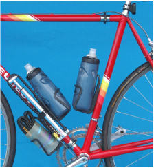
Figure 1. BFC locations choosen to make approximately equal size frame triangles
Design

The primary consideration for frame conversion is the location of the couplings and the routing of control cables around the couplings.  If your frame has internal routed cables it is recommended that you convert to externally routed cables.  Use of the Ritchie shift cable connectors is a straightforward method of breaking the shift cables. We recommend that the brake cables remain continuous and just remove the brake caliper assemblies to break apart the frame. (We have not yet converted a disk brake bike but the concept is the same).
Picture
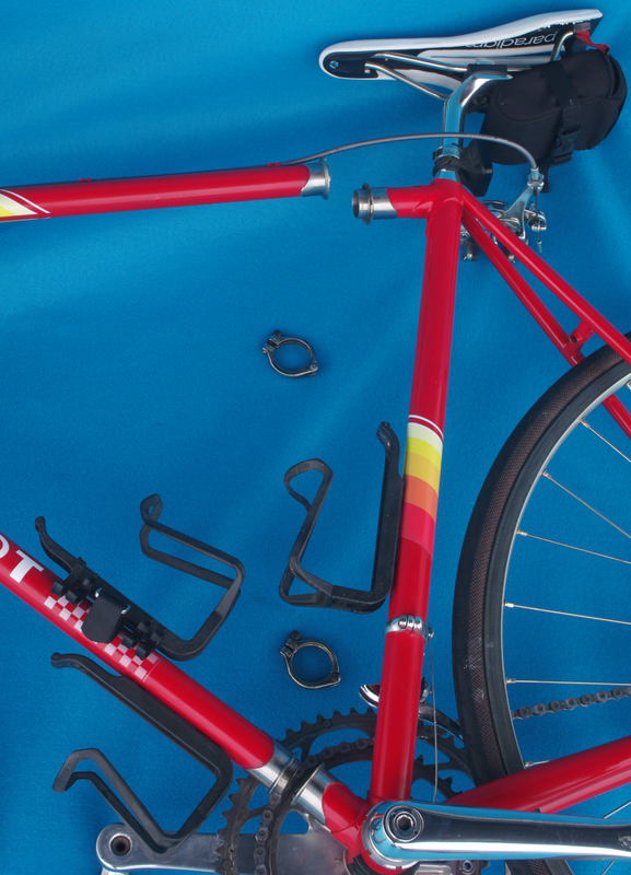
Figure 2. Cables are routed around BFCs
JBobs are generally located on the upper and down tubes as close to the seat tube as practical. Before you cut your frame apart, it is recommended that you select your travel case (see SandS.com) and make sure your break-apart frame will pack into the case.  Larger frames are a challenge to pack and sometimes require more than 2 couplings.  Scale drawings of the case and frame are recommended.
Picture
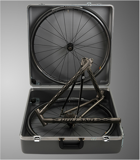
Figure 3. Holland's beautiful "Jet" bike in an SandS case
Considerations for coupling placement:

Packing in the travel case 
  •  Small movements in coupling location can make a big difference in the ability to fit the frame in the case – plan carefully

Control cable routing 
  • The rear brake cable usually routes outside of the top tube coupling.  If the coupling is close to a cable bracket, make sure there is room for a smooth cable path with large bend radii
  • Think about how to route the rear brake cable so as not to foul the rider
  • The front and rear derailleur cables generally route outside the down tube coupling.  Place the Ritchie shift cable couplings well clear of JBob
  • The outer shift cable usually terminates at the down tube shift bosses on vintage frames.  If you are shopping for a frame to convert look for these bosses.  If your frame does not have them, use a clamp-on cable stop available at bike shops or search for frame builders supply.

JBob Placement                             
  • Ensure the JBobs are not too close to adjoining tubes, brackets or lugs.  JBobs require a length of 60mm of constant tube outside diameter (OD), without obstructions, for installation
  • The JBob selection table lists the length of tube to be removed for each coupling size.  Use these lengths to identify two cut lines for each tube.  The centerline of the coupling will be equal distance from these two lines.

Frame Preparation (video coming soon)
  1. Strip frame of all components
  2. Locate the two cut lines for each JBob
  3. Remove all paint within 38mm (1.5in) of each line
  4. Measure the tube Outside Diameter (OD) at the cut lines with a good caliper or micrometer in several places around the tube to get a good average OD
  5. Choose the correct coupling size for each tube.  JBobs come in two sizes: 08 and 09 for 1, and 1 ⅛ inch OD tubes respectively.  JBobs are designed to slide fit over a perfectly round tube, having a 0.005 in diametric clearance.  If your tubes measure slightly larger than 1 or 1 ⅛ inch, or if they are not quite round, (common), that is not a problem. You can reduce the tube diameter for a clearance fit.  JBobs are not recommended for AVERAGE tube ODs less than 0. 980 in. for 08 JBobs or less than 1.105 in. for 09.  Contact us for a custom JBob size.
  6. Print this file and cut out the paper profiles for each selected JBob size and wrap them around your frame at the centerline of the JBob.   The template should wrap around the tube with minimal overlap or gap.  Insure that there are no frame parts that will interfere with the coupling.  Work around any interferences before you cut your frame!
  7. Make 4 perpendicular frame cuts (hack saw or abrasive wheel works well) at the cut lines and debur all edges.  Electrical tape at the outside edge of each cut line helps guide your cut and keep it perpendicular.
  8. From the tables select your  JBobs and options/parts and place your order.  Select the “D” or “P” options as desired.  Don’t forget to order enough clamps for brazing. 
  9. Carefully unpack your JBobs.   The couplings are assembled with a clamp (if clamps were ordered).  Do not mix coupling halves.  
jbob_design_and_installation_guide.pdf
File Size: 850 kb
File Type: pdf
Download File

Coupling Installation (video coming soon)
  1. Start with the frame half with the top tube Ferrule (or seat tube side if no top tube Ferrule)    
  2. Clean the tube down to bare metal for a length of 38 mm (1.5 inches) from tube end.    
  3. Test fit the coupling. If the coupling will not slide over the tube with hand assembly, use a flat file to carefully file the OD of the tube until the BFC can be installed by hand.  (The 3M pad with tool in a die grinder is great for careful diameter reduction.  For a clean look, finish the tube with emery paper/cloth with action perpendicular to tube centerline)
  4. Apply flux to the ID of the JBob and OD of the tube. Slide JBob half over the end of tube, making sure the tube end butts up against the Ferrule on the ID of the coupling.  If you are not using Ferrules, make sure the coupling mate line is halfway between your frame cut lines. Mark this position to ensure it does not move during brazing. 
  5. Rotate the coupling to align to lug pattern.
  6. If installing one alignment ferrule, it is recommended that the male end be on the seat end of the top tube coupling.  If installing two ferrules it is recommended that the second male end be on the fork end of the bottom tube coupling.
  7. Wrap the frame close to the coupling with damp towels and tape in place to minimize the heat damage to the existing paint.  If you are going to powder coat or repaint the frame, skip this step.
  8. Apply flux to the gap between the JBob and tube
  9. Heat JBob/tube to a very dull red color (recommend you do this without welding googles so you can see when coupling just starts to turn red.  Heat entire coupling evenly.  Apply silver solder rod.  At the proper temperature the solder will completely wet the seam between the BFC and the tube.  Work your way around BFC.
  10. Repeat steps 2-8 for the down tube JBob with Ferrule.  If Ferrules are not used install the down tube JBob on the frame half you started with.  You should now have two JBob halves installed, one on the top tube and one on the bottom tube. 
  11. Cool and inspect your braze joints - if there are any gaps between the tube and JBob, go back and reapply a bit of flux and braze.  Don’t worry about areas where you got too much braze we’ll take care of that at the end.    
  12. Clean the remaining tubes, apply flux, and slide the JBobs onto the frame.  Make sure the correct JBob mate is in the proper location.
  13. Remove the O-rings from a set of clamps and assemble the frame BFCs.  Rotate the JBob to align the lug pattern.  Carefully tighten each clamp a little at a time until the Ritchey hex wrench “clicks” indicating proper clamp screw torque (14 in-lbs).  Install the fork and check the alignment of the front fork with the rear drop out, generally no adjustment is needed but now is the time to make sure they are in line, rotate the fork to bring them into alignment.    
  14. Once you are happy that the BFCs are fully coupled and in the proper location, tack braze the JBobs in place by applying a small amount of braze rod in three equally spaced places around a “C” JBob, or braze the point and lobe of a “P” JBob.   DO NOT FULLY BRAZE THE BFC IN PLACE.  The reason for this is that there is a chance that the silver braze material could flow to the Ferrule causing the coupling to be brazed together.  After your tack joints have cooled, disassemble the couplings and complete the brazing of the couplings (If you are not using Ferrules this precaution is not necessary).
  15. A 3M Scotch Brite rotating pad in your drill motor or pneumatic die grinder is used to clean up the braze joint.  If you deposited too much braze in one area you can gently remove it with the pad (takes a bit of elbow grease).   
  16. Paint and install decals and you now have a custom fly-away bike frame!

JBob Templates

Picture
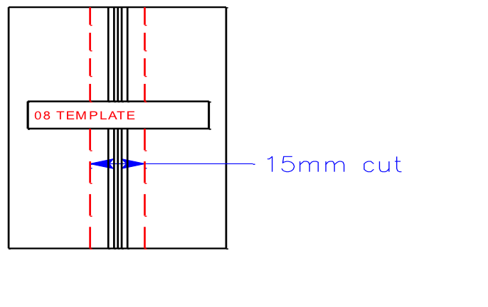
Figure 4. Download the JBob Design and Installation Guide PDF file to use this tempate
Picture
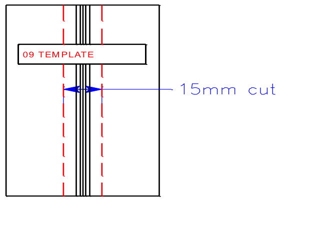
Figure 5. Download the JBob Design and Installation Guide PDF file to use this tempate
Home
Bicycle Frame Couplings
Contact Us
Blog
​This site is designed to provide the amateur and professional bike builder with all the tools and information needed for frame conversion or new bike design.
© COPYRIGHT 2015. ALL RIGHTS RESERVED.
  • Home
  • Bicycle Frame Couplings
    • JBob Design and Installation Guide
  • Contact Us
  • Blog